For those of you who have read the articles on this website, you will know that I have said on many occasion that I will absolutely in no way whatsoever build an aircraft model of any description!! This is mainly due to the fact that I am by trade an aerospace engineer and for the last 15 years I have taught the subject of aircraft maintenance engineering. The last thing that I want to do is to unwind at the end of a working day by making model aircraft!
This however is about to change. A conversation with my manager about the models that I make and display in my office led to the subject of large scale model aircraft. I mentioned that there are some pretty impressive models out there and showed him a few on the internet. I stopped on one particular web page that showed the Model Airways Sopwith Camel. I explained how the model was extremely detailed and that it would look fantastic in a display case in our hanger. Shortly afterwards I had somehow volunteered to build this for the University!
After a few weeks the model turned up from the USA and I was pleasantly surprised at the quality of the kit and a little daunted at its complexity. The kit is supplied in a large box with detailed A2 assembly drawings and a large amount of cast metal items to compliment the laser cut wood parts.


As always I will break the build of the kit into its main stages and keep the text to minimum essential descriptions only and let the photos tell the rest.
The Engine Build
The engine is all metal construction and is reasonably detailed. There are some casting marks that need to removed, however the metal is ductile enough to allow the use of a sharp blade in some instances to remove the marks. Construction is based around a central shaft and the first things to glue together are the 9 cylinders.I decided that I would paint the engine in a thin wash of Humbrol metallic black to give it an oily "used" look to add a little more realism:


Next up is the intake pipes. One of the first things that I realised that when the pipe was attached to the cylinder head via the valve; no one valve was quite the same fit as another. This meant that each intake pipe and valve would have to be filed to a size unique to that particular cylinder. You can see that each pipe was numbered to its corresponding cylinder. The pipes were also painted in Humbrol copper to resemble the real engine.


the valve guides and tappets were also cut to each particular cylinder size and attached as soon as they were the correct length. This was then followed by the spark plugs into each cylinder. The engine itself was simplistic in its construction save for the ignition wires. The instructions call for each wire to be tied to the top of the spark plugs (a trial in itself) and then glued using some cyno. The ignition ring that the wires attach to was a little more problematic as far as getting the tension right in the wires. I solved this by suspending the engine from two of my desk drawers, clipping a work holder to the wires and then using glue to hold the tension in the wires


There is still some more work to complete the engine, however I have decided to finish the detail work once I am at the point of mounting it into the air-frame. I have also soldered up a quick engine stand to store the engine whilst the rest of the work on the Sopwith is being done.
The Propeller
The propeller is made from three laminates which must be glued and clamped together followed by carving and sanding to its final shape. Considering that this can be quite a detailed task and that you only have one chance to get it right, its quite daunting!


While carving the prop to my horror a small sliver of wood chipped off from the centre!! Fortunately I had the forethought to save some of the sawdust from the prop in a small bag for this very reason. Mixing the sawdust with some PVA glue will give you an instant wood filler that is exactly the right colour!


Although the instructions do not dictate in any way that the propeller should be balanced, I felt that this was something that I had to do as a matter of personal pride (plus I work with some very talented engineers who would endlessly remind me that the prop wasn't balanced if they found out!) I won't go into the description of how to balance a prop as this is something that is unnecessary for a static model, but I had to mention it here as it added at least 8 hours to the build time of this model to do it!
The instructions say that the prop should be painted in English Oak stain. While I am sure that this is 100% correct, I have decided to use a little artistic licence and leave the prop in its natural colour and apply some high gloss varnish to bring out the detail in the lamination's and provide a lighter contrast to the oak stained air-frame. I will probably make a few more decisions like this being as it is intended as a display piece once finished and I am happy to sacrifice complete accuracy in the pursuit of aesthetics.
The instructions say that the prop should be painted in English Oak stain. While I am sure that this is 100% correct, I have decided to use a little artistic licence and leave the prop in its natural colour and apply some high gloss varnish to bring out the detail in the lamination's and provide a lighter contrast to the oak stained air-frame. I will probably make a few more decisions like this being as it is intended as a display piece once finished and I am happy to sacrifice complete accuracy in the pursuit of aesthetics.
.


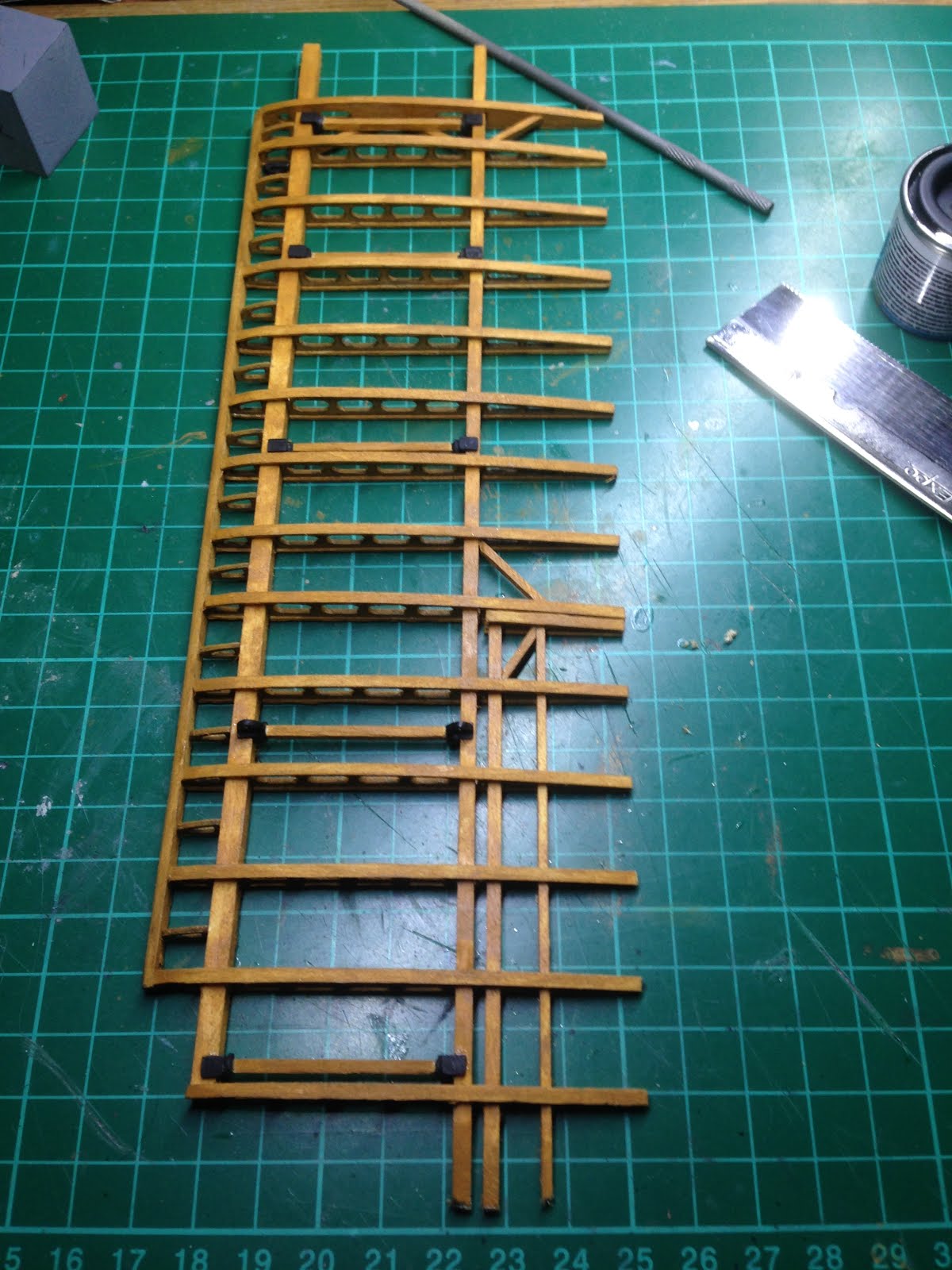
The Wings
The wings are supplied as strip wood and laser cut wooden ribs. The whole thing has to be built from scratch with reference to the supplied drawings. Fortunately I have access to an A3 photocopier, laminator and reams of blue foam. The different sections of the drawings were photocopied, laminated (to prevent the glue from adhering to the paper) and then mounted onto some blue foam. This set up would allow me to accurately line up each of the ribs directly on the drawing, apply glue at the appropriate points and then pin into place to allow the glue to dry. I will make no attempt to sugar coat this; the basic construction of the wings is as much of a challenge in endurance as it is in terms of modelling ability!!! I also ran into some problems with the fitment of the wing tips: they didn't fit! To remedy this I got hold of some brass rod and made some new tips with the drawings as reference. In addition the compression bars are supplied as one piece metal items, however on the real aircraft these are made from wood. The obvious choice is to paint them to mimic wood but being as they will be placed next to real wood this would be difficult to the point of impossible to do. I opted to cut the mounting ends of the bars, cut some stock wood from my personal supply and re-make the compression bars., This was a little more work but I am sure that you will agree that the extra effort makes for a much more visually appealing end result.
I also got into a little trouble with my long suffering wife when she realised that I had sellotaped one of the drawings to the back of the sofa while I used it for reference. I'm now forgiven but for a moment there it was touch and go!!


During the construction of the wings I decided that I would paint all of the metal parts in matt black with a final coat of satin varnish over the entire wing area leaving a satin black completed finish. After a little research I discovered that the majority of Sopwith aircraft at the time has a satin or gloss coat of coach paint to increase the life of the metal. While some shiny brass rods would look nice on the finished piece; the combination of white metal, brass and copper which is used in the other wing components would in my opinion look a little odd. I will also admit at this point to a mistake in the wing construction. For the two lower wing section leading edges I glued the wrong size wooden strips in place (it was late at night!) and didn't realise my mistake until I had carved them to their final shape. The strips that I had used were intended for the inter wing mounts! As a result I have had to order some new strip wood for a small amount from the USA. Fortunately The time it will take for the wood to arrive will not slow down the progress of the build as there is so much more work left. I'm going to chalk this mistake down to experience and regard it as quite lucky in the sense that it didn't cost a lot in money terms and nothing in terms of construction time.
When it came to rigging the wing I was a little apprehensive as this is something that I have not attempted before. I borrowed an additional fine pointed tweezers and hoped for the best! Again like so many other jobs on this kit; the key to success is patience and concentration. The rigging looks really good when finished but care must be taken to ensure that each and every line is kept taught throughout the entire process:


The fuselage
The fuselage is built from stock wood parts and assembled in a similar way to the wings for the first stages on some blue form board and laminated plans. For the remaining part of the build a few jigs will have to be made to ensure that the fuselage construction remains true. I will make a huge point of saying that the accuracy of the jigs will play a massive role in the finished fuselage so please take your time in building these if you are attempting the same or a similar model. I will also be retaining these jigs and the engine stand for a while in the spares box and if you would like them I will be more than happy to send them to you for free as long as you don't mind covering the postage costs.


The fuselage assembly went together relatively easy. I did pay a great amount of attention to keeping things square and true at every stage. From an accuracy point of view I have used a digital vernier caliper, steel rule and engineers square throughout the build and it was never more important than the fuselage construction. There is a risk of accumulative error* when building the frame so patience is a must.
*where one small error builds in errors for each and every stage after resulting in a warped or misaligned frame at the end of the build
There are a number of metal components for the fuselage and in the most part they are easily put together, primed and painted. The fuel tank however presented a huge problem. The casting was awful! I didn't want to use too much filler as its difficult to shape such a large amount of filler and get it right. I opted to solder the two halves of the tank together and add some additional solder with a gentle flame and file back to the intended shape of the tank. Fortunately for me the other two tanks for this aircraft were not in as bad shape and these were simply glued together and filed to final size.


The engine mounting frame that attaches to the front of the fuselage assembly is supplied as a one piece casting. The instructions mention that there is also a firewall fitted between this and the engine but has been omitted from the kit. I can appreciate that this is omitted for aesthetic reasons but the aircraft engineer in me just can't allow the assembly of this aircraft without the inclusion of this firewall. Put simply, the engine would never be fitted without one! Fortunately I have access to a large amount of aluminium sheet at the university and being as this is being built for them I can happily use some of it for this build in good conscience. I also noticed whilst conducting some research that the engine mounting frame was wrong. There are too many supporting bars on the kit supplied item when compared to the real thing. This was removed and re-sprayed in matt black.


The cockpit builds up into a really nice representation of the real aircraft. The rudder bars and control column are allowed to move freely, the detail is very good and there is also the opportunity to add wires and pipes to the entire area with some pretty comprehensive instructions and diagrams. I would point out that each part requires some considerable clean up to get it to fit accurately, but with a little patience and lots of concentration the whole cockpit builds up very well.


After the cockpit was built I found that I kept looking at the area and thinking that something was missing. I had looked at a few of other Sopwith kits that had been built in the past and some of the modelers had opted to build the additional frames around the cockpit. I had originally decided that I was not going to add this detail, but the more and more that I looked at the kit that I was building I realised that it had been stripped back a little too much by the manufacturer, and really did need these extra frames to "look right". The frames were made from bass wood strip cut and filed to size by hand. The whole process was time consuming and frustrating to get right but in my humble opinion looks great and provides a whole new depth of interest to the kit. I also cut some additional metal parts to add to the rear of the fire wall that replicate the cooling ducts on the real aircraft.


The next major part of work for the fuselage is the bracing wires. I won't go in depth for the process as this was essentially covered in the wings section of this write-up. I have kept the lower bracing wires till a last minute job as I want to retain the access to run the control wires first. I also decided to add the wooden cover for the fuel tanks as this is another part not provided with the kit but I feel adds to it and makes it look a little more like a Camel. To make I simply soaked some balsa in water for 30 minutes or so and then dried it in a curved position and cut to fit once dry.


Following the completed fuel tank cover I realised that I had to make the cockpit coaming to complete "the finished look". Again this was made from soaked and cut balsa. The construction of this was a little more troublesome than I expected; however after a little perseverance I achieved the correct shape for cockpit coaming. To finish the "look", I used some more of my old leather wallet to edge the coaming as per the actual aircraft.


Tail Section
The horizontal tail section was a simplistic build in that its a smaller version of the wings. It went together very easily and there are no major problems to speak of. The Vertical stabiliser (fin) and rudder however are a very different story: When you take the kit fin and rudder and place them up against the fuselage it looks great; it does not however look great when the horizontal surfaces are mounted and then the vertical surface is added. The problem is that the horizontal surface if mounted according to the kit instructions is completely the wrong angle. Anyone who knows anything about aircraft would spot it a mile away. In simplistic terms the aircraft, if built in that way would constantly want to nose dive into the ground!! This is something that I could not ignore when one considers that the kit will be on display in a university building that specialises in aircraft engineering!!
The first stage of remedying the problem was to raise the tail section of the fuselage using block wood. Next, the rear blocks of wood placed there in accordance with the kit instructions and drawing were removed as these are not present on the real aircraft. The tail section was test fitted and once I was happy that it sat in the right angle, the whole area was re-painted. The next problem was that the rudder is now too small for the modified area. I opted to make a complete new rudder from brass rod and modify the fin to fit by adding some additional plastic strips to match the shape of the support bar.


Other small modifications
There are a number of small metal parts provided in the kit that I decided to modify slightly. Some of these modifications were made to provide a little more realism and detail, while others were carried out to amend a casting defect or omission of detail.
The fuel gauge was modified with a piece of clear plastic sprue to represent the glass tube section that fills with fuel to tell the pilot just how much he has left in the tank. To get the right diameter I placed the sprue in the chuck of my small drill and put it on low RPM's while filing down with a file and then some very fine emery cloth. The white metal tube was then cut away and replaced with the turned sprue section:


The machine guns took a lot of work to look right. The whole casting was cleaned and filed, the bullet ejection port was drilled out and the gun barrel removed. The water jacket was drilled on the end and then a new two piece gun barrel was made from stock plastic tubes and fitted to the part.


The ammunition magazine and empty case ejection ports are supplied as a one piece casting and is nothing more than terrible. The top section of the part that I had was miscast and had to be built up and the ejection ports are too short to clear the fuselage. The original ports were removed and replaced with some new longer items. I would also point out that the ports must be fitted separately to the magazine after it has been glued into the fuselage. if you glue them back together as a one-piece before fitting it will physically not fit into the air-frame.

The tail skid assembly is a good representation of the actual item on the aircraft however on the real aircraft this is not an all metal component. I shaped a small amount of bass wood to replicate the curved section of the skid, then cut the various sections from the supplied part. The difficult part to remove is the mounting point, which has to be cut, filed and then drilled to fit the wooden skid correctly. I pinned the mount to the skid using some brass rod which allows the skid to move freely as seen on the real aircraft. Being as the part now physically moves I will also be replacing the black string supplied with the kit with some elasticated string or the slightest movement of the skid will cause the string to unravel whereas the use of elastic under tension will ensure that this does not happen and hopefully it will operate as the original does:


To fit the skid to the tail section the original plans assume that the rear support bars are still there. I had previously removed these as they are not on the real aircraft, and their removal formed part of the modified tail section that I have described earlier on in this build diary. On the original aircraft the skid is mounted via a welded tube from the tail assembly however I opted not to replicate this as I believe it would not be strong enough to support the suspension I intend on building with the materials that I have available. I opted to insert a small shaped block of wood into the lower part of the fuselage frame which should support the tail skid mount whilst still maintaining a very close resemblance to the real aircraft. I would also point out that the flanged brass insert provided with the kit has an internal diameter that is far too large to provide a close tolerance fit for the tail skid. This was remedied by fitting the original insert and then filling with some plastic rod, then re-drilling the insert at the correct diameter; the added bonus being that that plastic inside the brass insert allowing for a small amount of self lubrication against the metal pin of the tail skid.
The upper part if the tail skid assembly is a simple brass rod that is mounted into either side of the upper fuselage. The small bungee cord is wrapped from there and onto the notched section of the tail skid. When fitted the whole assembly doesn't just look the part; it actually works as well! I'm really happy with the finished assembly and it was really worth the extra thought and work in my opinion.


The wheels provided with the kit didn't resemble any of the photographs that I have seen of the Camel and after a little research it turns out that the manufacturer is attempting to display the wheels as having the fabric covers attached and opted to use the wheels from another kit that they produce. While they have similarity, they could be a lot better. In order to match with the real wheels as much as possible I removed all detail from the kit items and filled the circular holes with some squadron putty. The covers were then drilled to replicate the holes to enable the tyres to be pumped from time to time and then the whole thing was sanded and primed.


I also decided to replace the hideous pilot seat that was supplied with the kit. For the base I used some scrap thin ply from the fret I had with the kit, the back rest was made from copper wire and the wicker is in fact sea-grass from a very cheap (£1) hanging basket that was unwound, stripped and then used to make the rest of the seat. An old leather wallet completed the look by cutting off a portion of leather that still had the stitching intact and looks like I actually took the time to sew into the seat. I also made a small leather seat pad to add to the completed model. This was a little time consuming but ultimately enhances the kit so much when viewed against the original kit part.


Pilot's foot hold
I was a little surprised that this wasn't included with the original kit. The addition of the part is one of those "you wouldn't notice it if it wasn't there" items but once it's fitted you wouldn't want to take it away again (if that makes sense). The foot hold was easy enough to make from some aluminium soda can (or if your welsh a can of pop!). I also wanted to make it look well used so once it had been cut and filed to shape I battered it slightly by repeated crushing with a small pliers before painting.


The engine cowl
The kit doesn't have a supplied engine cowl so that once built the entire engine is on display. I can see the manufacturers reasoning behind this, however to me it somehow doesn't look quite right? Fortunately I have access to a 3D printer at the University and being as this particular model is being built for them I spoke very nicely to one of our technicians, supplied him with a copy of the engine cowl drawing that I found on the internet and printed an engine cowl. The photos below are of the cowl being printed in a rough draft format for test fitting:


The rough draft version flagged up a few minor problems in that the internal diameter was a little too large and the depth of the cowl needed tweaking slightly as well. The CAD drawing was altered to reflect this and the final high quality print was made. I opted to finish the interior of the cowl in a dull aluminium colour to reflect what you would see on the real aircraft. I was a little torn in the external finish; I originally planned to smooth the outer surface and paint in alclad to give a chrome finish to the cowl, however apart from the hours of prep work, this has been done a number of times on these models. Instead I went with the second option that I had which was a cherry red colour to match the University of South Wales colours and would also match the wheels. The following photos show the finish of the cowl:


Joining the major sections
The first step that I decided to take was to test fit the undercarriage section to the fuselage. I was considering for a time to replace the undercarriage mounts with wooden items, however after a little research I discovered that the uprights were either painted silver or black, so if I did replace with wooden uprights and painted them; they would end up looking exactly the same! I was also considering modifying the wheel mounts to allow for the suspension element of the undercarriage to work. I had seen this done by another model maker on the same kit. After a little thought I decided against this as it would not make any real aesthetic difference to the finished item. With this modification knocked off the "to do list" I removed the casting marks from the parts, primed and then sprayed in satin black.


The lower wings were simplistic to fit and allowed to set prior to the undercarriage legs being fixed into their position. The upper wing took a little more work as I decided to replace yet more of the metal parts supplied with the kit. The cabane struts from the cockpit are supposed to be wood and not metal. The end fittings were cut from the metal struts and new ones made from bass wood. The correct angle was difficult to achieve. Fortunately everyone who lives in my house is over the age of 18, as the language around my model desk became a little "blue" while I set the top wing in place:


The remaining assembly of the model was really easy as the "difficult" bits had already been completed. Careful planning and preparation was all it really took to complete for me a marathon build!! This is one of the most challenging models that I have made to date as I normally take quite a lot of artistic licence in my models to create that aesthetic look I strive for. In this instance it had to be right and many hours were spent over the smallest detail to ensure that this model was a close to realism as I could get. I hope that you enjoyed reading how each of the sections were completed and as always I welcome your comments.


More pictures when the display case arrives........
Got this kit for Christmas and your descriptions & photos will be valuable tools as I move forward with my kit. Wish me luck!!!!!!!!
ReplyDeletehi
ReplyDeletesorry for the late reply. I hope that you have loads of fun building this as I did. I have since bought another kit like this and will be building it sometime in the future